
RBEs and MPCs connect the motion of one node to one or several other nodes, and they are among the most misused tools in finite element modeling. This Book Byte explains the terminology across Nastran, Ansys and Abaqus, the difference between the rigid element (RBE2) and the interpolation element (RBE3), the rules to set up an interpolation element correctly, and when to write your own multi-point constraint.
Overview and terminology
RBEs and MPCs are used when we need to connect the motion of a node (translations and/or rotations) to another node or to several nodes. MPCs and RBEs define equations of constraint between the degrees of freedom of the nodes involved in the connection.
- Multi-point constraint (MPC): a constraint that involves user-selected degrees of freedom. The user must compute and manually input the coefficients of the equations of constraint.
- Rigid body element (RBE, R-type): specialized inputs of MPC equations. The user only specifies the degrees of freedom involved in the equations of constraint; all the coefficients are calculated internally by the FEA software.
MPCs or RBEs can be used to model rigid bodies and rigid constraints, but not all RBE elements are rigid.
| Element type | Number of nodes | Geometry based | User-input based | Description |
|---|---|---|---|---|
| Rigid RBE (R-type) | Arbitrary | Yes | Rigid body with independent DOFs at one node and dependent DOFs at an arbitrary number of nodes. Really rigid elements, off the shelf. | |
| Interpolation RBE (R-type) | Arbitrary | Yes | Yes | Defines the motion of a reference node as the weighted average of the motions of a set of nodes. A distributed constraint for applying remote loads without making the connection overly stiff: it is flexible and does not add stiffness. |
| Constraint (MPC) | Arbitrary | Yes | Constraint equations used to connect specified degrees of freedom. Handmade. |
Any combination of these elements may be used in an FEA. However, they should be used with care in geometric nonlinear analysis.
Terminology in Nastran, Ansys and Abaqus
The three major FEA codes offer RBE and MPC capabilities, but the terminology varies:
| Nastran | Ansys | Abaqus | Generic terminology | |
|---|---|---|---|---|
| Rigid element (R-type) | RBE2 | CERIG | Kinematic coupling | Rigid |
| Interpolation element (R-type) | RBE3 | RBE3 | Distributing coupling | Compliant |
| Multi-point constraint | MPC | MPC | MPC |
Introduction to R-type elements (RBEs)
An R-type element is mathematically equivalent to one or more MPC constraint equations. Each constraint equation expresses one dependent degree of freedom as a linear function of the independent degrees of freedom.
RBE elements impose fixed constraints between components of motion at the nodes to which they are connected. They are sometimes called rigid elements, but the term "rigid" is misleading. There are two kinds:
- N-node rigid element: a rigid connection between an arbitrary number of nodes (infinitely stiff).
- Interpolation element: a connection between an arbitrary number of nodes (no stiffness).
Important points about R-type elements
- R-type elements are based on a linear displacement relationship, not an elastic relationship.
- R-type elements are not dictated by stiffness, mass or force.
- R-type elements follow small displacement theory, so they should be used with care in geometric nonlinear analysis.
- Some R-type elements have different definitions for dependent and independent nodes.
- The stiffness, mass and loads at the dependent DOFs are transferred to the independent DOFs.
The rigid element (RBE2)
The N-node rigid element defines a rigid body whose independent degrees of freedom are specified at a single node and whose dependent degrees of freedom are specified at an arbitrary number of nodes.
- It is a very convenient tool for rigidly connecting the same components of several nodes.
- It artificially adds stiffness by constraining the system to follow a linear translational and/or rotational relationship between the connected nodes.
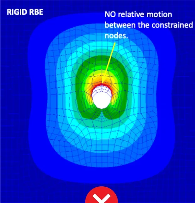
- It does not allow any relative motion between the dependent nodes (undeformable).
- Consider using it where the load path is stiff. Otherwise, use an R-type interpolation element to transfer the load.
Key points:
- Connects an arbitrary number of nodes
- One independent node with multiple dependent nodes
- Independent DOFs specified by the user
- Artificially increases the stiffness of the structure
- No relative motion between the dependent nodes, so no deformation between them
The interpolation element (RBE3)
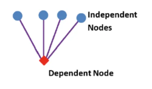
With the interpolation element, the loads and mass applied at a dependent node are distributed to an arbitrary number of independent nodes.
- The interpolation element is NOT a "rigid" element.
- It does not add artificial stiffness to the structure.
- It allows warping and 3D effects.
- The reference node is the dependent node (the single node at the tip of the element).
- The dependent degrees of freedom cannot be constrained with SPCs.
- The dependent degrees of freedom cannot be part of another RBE element or MPC equation.
The main purpose of the interpolation element is to transmit forces and moments from a reference point to several points.
The interpolation element can produce unwanted mechanisms if there are not enough independent degrees of freedom to resolve the applied loads and moments for static equilibrium. Take care when defining it: in general, three or more non-collinear independent nodes will work for all degrees of freedom.
Four rules to set up an interpolation element
- Load distribution: the distribution of the applied loads is based on the geometry of the interpolation element and on the weighting factors.
- Complete motion: the independent degrees of freedom must be able to describe all the motions of the dependent node. If not, the solver issues a fatal error.
- Translations only: only the translational components are used for the independent degrees of freedom. The rotations of the dependent point are fully defined by the translational motion of the independent nodes (think in terms of the free body).
- Rotations for special cases: the ability to input rotational independent degrees of freedom is reserved for special applications, such as when all the connected nodes are collinear.
Key points:
- The interpolation element is linear.
- Do not specify rotational DOFs for independent nodes, except when necessary to avoid singularities.
- The independent DOFs must be able to describe all the motions of the dependent node.
- The relationships are calculated from the initial geometry.
Rigid (RBE2) or interpolation (RBE3)?
To choose between a rigid and an interpolation RBE, answer the following questions:
- When loaded, do you expect the nodes of the RBE to move together (rigid, RBE2) or independently (interpolation, RBE3)?
- Will stiffening a portion of the model with RBEs change its overall deformation behavior?
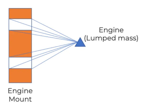
Example: engine mounts. With a rigid RBE, all mounts deform together. With an interpolation RBE, each mount takes a different displacement based on its local stiffness.
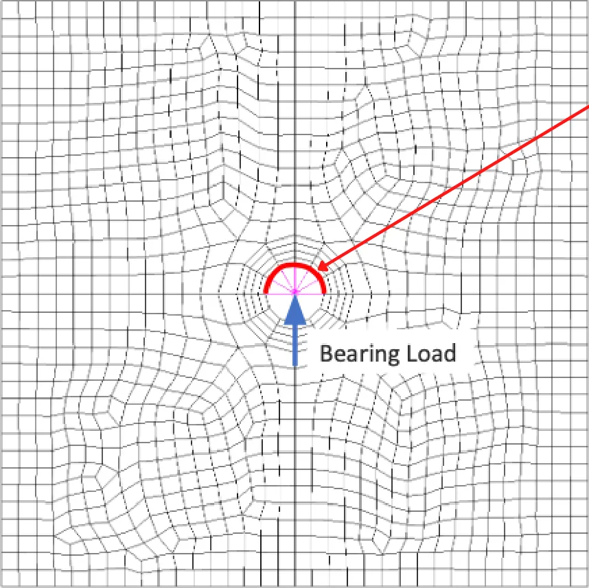
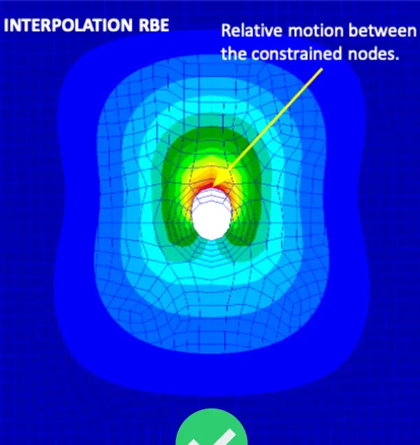
Example: bearing load in a hole. Here, relative motion between the constrained nodes is expected, so the interpolation element is the correct choice.
Multi-point constraints (MPCs)
RBE elements are convenient for the user: the FEA software automatically generates the constraint equations for each dependent degree of freedom, depending on the definition of the element.
The MPC is a generic constraint and the most general way to define motion-based relationships. With an MPC, the user must:
- Select the degrees of freedom
- Compute and supply all the coefficients of the MPC equation
Definition of a multi-point constraint
The motion of a degree of freedom depends on the motion of at least one other degree of freedom:
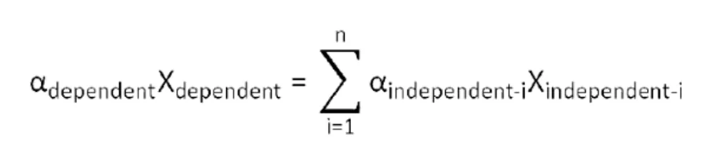
where αdependent is the coefficient of the dependent degree of freedom, Xdependent the dependent degree of freedom, αindependent-i the coefficient of the i-th independent degree of freedom, and Xindependent-i the i-th independent degree of freedom.
What MPCs can be used for
- Tie nodes together (although an RBE element is better in this case)
- Define the relative motion between nodes
- Enforce a separation between nodes
- Define the average motion between nodes
- Create a linear contact between nodes
- Create a preload in a bolt
Go further
This Book Byte is taken from Chapter 12 of Practical Finite Element Analysis for Mechanical Engineers by Dominique Madier. The topic is covered in depth, with worked examples, in the on-demand course Practical Basic FEA.
See the Practical Basic FEA course Take the free FEA diagnostic