
Knowing what finite element analysis is does not tell you how it is used day to day. In an engineering organization, FEA is not an isolated computation: it is a decision tool that supports stress engineers, dynamics engineers, loads engineers and designers throughout the life of a product. This article looks at FEA from the practitioner's point of view: who benefits from it, which questions it answers, the industries and physics where it is used, the FEA process seen by the engineer and by the solver, what commercial software can do, how accurate the results really are, and the inputs you must define before you can run your first analysis.

How FEA can help you
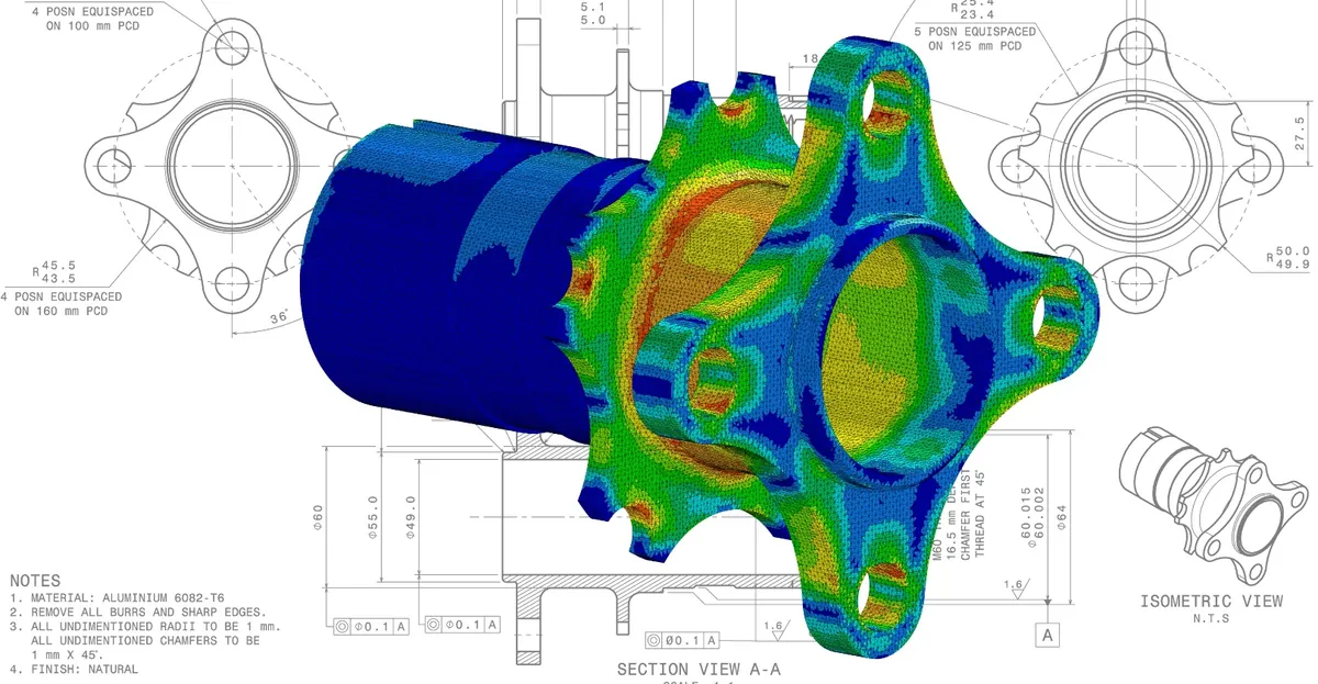
FEA is helpful for all the specialists involved in product development, not only for the analyst who runs the software.
- Stress and structural engineers use FEA to compute stresses and strains and to verify that each part has enough strength, stiffness and life.
- Dynamics engineers use it to predict natural frequencies, mode shapes and the response of structures to vibration and shock.
- Loads engineers use it to determine how external loads are distributed through a structure and to extract the internal loads applied to each component.
- Designers use it to compare design options early, before a detailed drawing is released.
The seven questions FEA answers
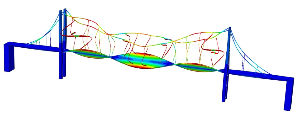
FEA helps all these specialists make decisions during every phase of product development. In practice, it answers seven questions:
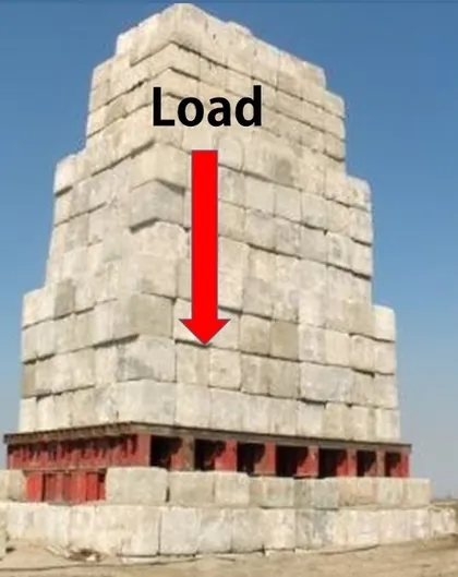
- Will it break?
- Will it deform too much?
- Will it hold together?
- Where are the weakest points?
- Can it be lighter?
- Can it be stronger or more durable?
- Will it work the way it was designed to?
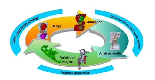
The first four questions are about safety and integrity. The last three are about performance and optimization. A mature engineering team uses FEA for both: not only to check that a design is acceptable, but also to make it better. Each loop of the design cycle, from design to simulation, analysis of the results and validation, saves cost and time, improves innovation and optimizes product performance.
Seven typical situations where FEA is used
There are seven typical situations in which engineers turn to FEA.
- Solving complex engineering problems. FEA is useful for problems with complicated geometries, loadings and material properties, for which analytical solutions are not applicable.
- Solving multiphysics problems. FEA can couple several physical phenomena, for example thermal and structural effects, and provide solutions that would be impossible to obtain with classical methods.
- Predicting the response of mechanical structures to environmental factors such as forces, pressure, temperature and vibration.
- Saving time and cost. FEA is an important part of the design phase in an iterative development process, because it saves engineers time and reduces the effort and cost associated with building physical prototypes.
- Determining deformations and stresses. During product development, simulation software with FEA functionality is used to define the deformations and stresses that components will undergo when subjected to environmental factors.
- Defining the critical dimensions of a component by considering factors of safety, weight and other parameters. Used intelligently, FEA packages are extremely powerful sizing tools.
- Analyzing interactions between parts. An analysis can be as simple as a single part whose behavior you wish to capture, but it can also involve multiple parts whose interactions you want to predict.
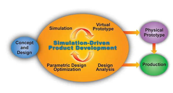
Areas where FEA is used
FEA is now used routinely to solve problems in a wide range of areas. Here are the main ones.
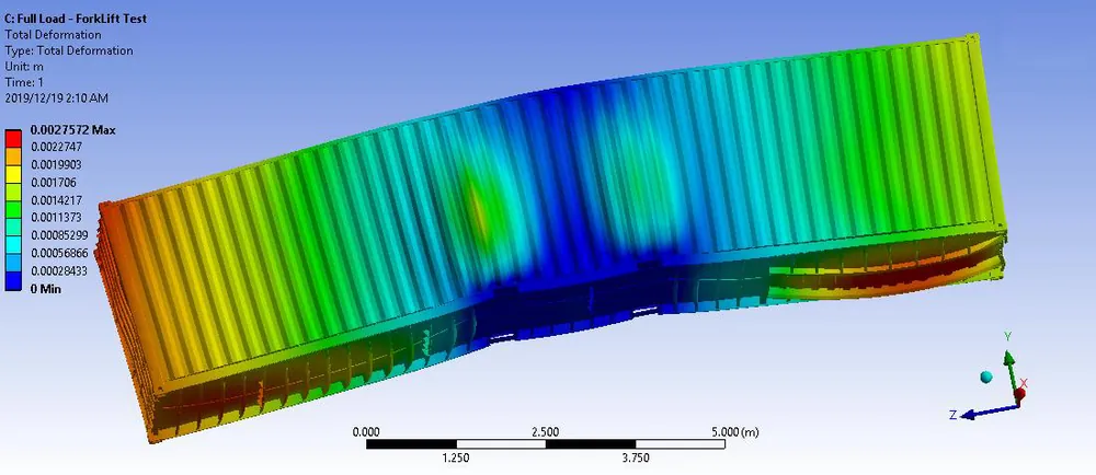
Structural strength design
This is the historical and most common use of FEA: verifying that a structure can carry its design loads with an adequate margin. Bridges, aircraft, vehicles, pressure vessels and machine parts are all sized this way.
Structural interaction with fluid flows
Fluid-structure interaction couples the pressure of a fluid with the deformation of the structure, for example for a pipe conveying a fluid, a wing in an airflow or a tank under sloshing loads.
Acoustics
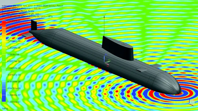
Acoustic analysis predicts how sound propagates around and through a structure, and how vibrating panels radiate noise. Applications range from passenger comfort in cars and aircraft to the acoustic signature of a submarine.
Thermal analysis
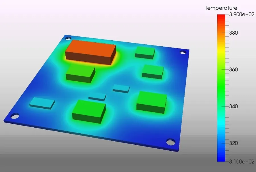
Thermal analysis computes temperature fields and heat fluxes, either in steady state or as they change over time. The temperatures can then be applied to a structural model to compute thermal stresses, as in the electronic board below.
Vibration
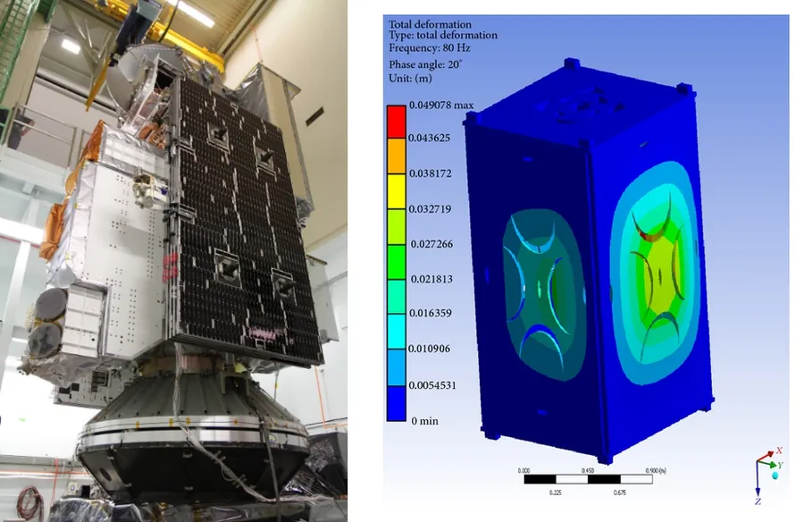
Vibration analysis determines the natural frequencies and mode shapes of a structure and verifies that they do not coincide with the excitation frequencies of its environment. A satellite, for example, must survive the vibration environment of the launcher.
Crash simulation
Crash simulation reproduces the very fast, highly nonlinear events of a vehicle impact, with large deformations, contact and material failure. It has drastically reduced the number of physical crash tests needed to certify a car.

Fluid flow (CFD)
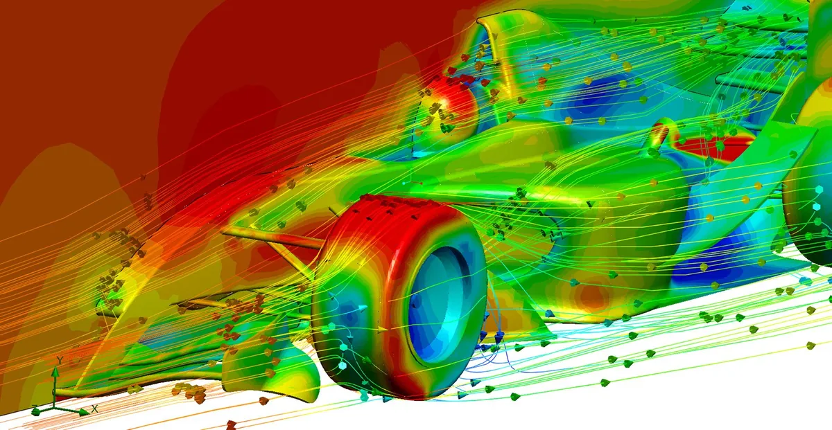
Computational fluid dynamics predicts velocity and pressure fields in liquids and gases, such as the airflow around a race car. Although the finite volume method is generally preferred for CFD, the results often feed structural finite element models with pressure loads.
Buckling problems
Buckling analysis determines the load at which a slender or thin-walled structure becomes unstable. Columns, stiffened panels and thin tubes are typical candidates.

Dynamic analysis
Dynamic analysis computes the response of a structure to loads that vary with time, such as the meshing forces in a gear train, impacts or earthquakes.
Electromagnetic evaluation
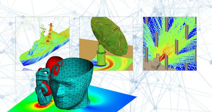
FEA also solves electromagnetic problems: the distribution of electric and magnetic fields, antenna radiation, and electromagnetic compatibility.
Metal forming
Metal forming simulation reproduces processes such as stamping, bending and forging. It predicts the final shape of the part, thinning, springback and the risk of tearing or wrinkling.

FEA at every stage of the product life
FEA is useful at every stage of product design:
- Before the product is defined, FEA helps the engineer create a feasible design by comparing concepts and sizing the main components.
- After the product is designed, FEA validates the defined design against its requirements.
- After the product is released, FEA can be used to investigate failures and to qualify repairs or modifications.

Put simply, FEA lets engineers make great products by delivering better designs quickly.
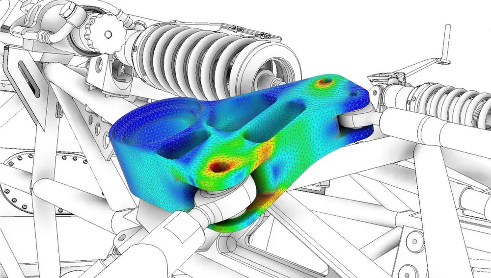
The FEA process from the engineer's perspective
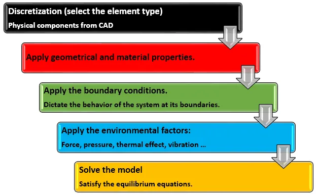
When an engineer works with FEA, the process follows five basic steps.
- Discretization. Select the element types and mesh the physical components defined in the CAD.
- Apply the geometrical and material properties. Thicknesses, cross sections and material data are assigned to the elements.
- Apply the boundary conditions, which dictate the behavior of the system at its boundaries.
- Apply the environmental factors: forces, pressure, thermal effects, vibration and so on.
- Solve the model, so that the equilibrium equations are satisfied.
The FEA process from the solver's perspective
From the solver's perspective, the process is different. The solver does not see geometry or CAD; it sees matrices.
- Evaluate the stiffness matrix [K]e of each individual element.
- Assemble the global stiffness matrix [K] of the analyzed system.
- Apply the loads and boundary conditions.
- Solve the equilibrium equations to obtain the displacements, which are the primary variables.
- Calculate the secondary variables: forces, stresses, strains, velocities, accelerations, energy and so on.
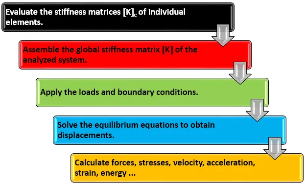
Notice that the solver works on displacements first. Stresses are never computed directly: they are derived from the displacements through the strain-displacement relations and the material law. This is why an error in stiffness or in the constraints affects every result downstream. Understanding both perspectives is important. The engineer's process explains what you must do. The solver's process explains why the quality of each input matters: a wrong property, a missing constraint or a badly connected mesh ends up in the matrices, and the solver will faithfully compute the consequences.
Capabilities of FEA software
Commercial FEA software can solve a wide variety of single-physics and multiphysics problems, including structural problems, heat transfer, fluid dynamics, acoustics, magnetism and electric fields. Structural engineers use FEA to ensure that a structure has the necessary strength, stiffness or life to prevent failure, whether that failure comes from excessive stress, resonance, buckling or detrimental deformation.
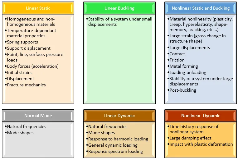
The structural capabilities are usually organized into six families of solutions:
- Linear static: homogeneous and nonhomogeneous materials, temperature-dependent material properties, spring supports, support displacements, point, line, surface and pressure loads, body forces (acceleration), initial strains and fracture mechanics.
- Linear buckling: stability of a system under small displacements.
- Nonlinear static and buckling: material nonlinearity (plasticity, creep, hyperelasticity, shape memory, cracking), large strains, large displacements, contact, friction, metal forming, loading and unloading, stability under large displacements and post-buckling.
- Normal modes: natural frequencies and mode shapes.
- Linear dynamic: natural frequencies, mode shapes, response to harmonic loading, general dynamic loading and response spectrum loading.
- Nonlinear dynamic: time history response of nonlinear systems, large damping effects and impact with plastic deformation.
FEA outcomes
What do you get at the end of the analysis? For static and buckling analyses, the outputs include displacements, forces, reactions at supports, the stress tensor, principal stresses, equivalent stresses (Tresca, von Mises), strains, strain energy, stress intensity factors for fracture mechanics, and buckling factors with their associated shapes. For dynamic analyses, they include natural frequencies, mode shapes, modal mass fractions, and the response to loading in terms of displacement, velocity, acceleration, force, reactions, stress, strain and energy.
How accurate is FEA?
FEA predicts the approximate response of a structure under a given excitation, so a legitimate concern is the accuracy of that prediction. Accuracy depends first on the differences between the real structure and the finite element model.
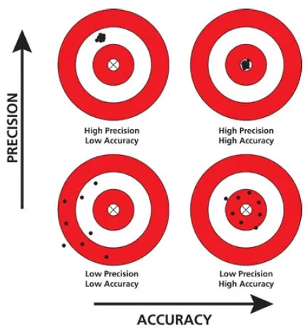
The targets above recall an important distinction. Precision is the ability to obtain the same result every time; accuracy is the ability to obtain the right result. A finite element model is perfectly precise: run it twice and you get the same numbers. Whether those numbers are accurate depends entirely on the assumptions built into the model.
A perfect match between reality and the model is impossible, because many assumptions are made when the model is built:
- Assumptions on the CAD, when the geometry is discretized by meshing the parts that compose the structure.
- Assumptions on the modeling of joints.
- The choice of material models.
- The discretization of the real loads into forms the finite element model can understand.
- Assumptions on the boundary conditions.
- The behaviors the analyst decides the model will capture.
Each of these assumptions produces a deviation between the real structure and the model. There is no way to determine the true error of an analysis, but you can attempt to quantify the effect of each assumption to obtain a relative error. For example, analyzing a bounding range of material properties reveals the error introduced by the material response. For steel structures, this error is very small, since the modulus of elasticity of steel varies by less than 1%. For soil, on the other hand, the error in the material response can easily reach 20%.
In most analyses, the largest error comes from bad boundary conditions. Incorrectly supporting a model can create large errors that remain invisible to the user, because the solver still returns a smooth, plausible-looking result.
When it is done well, FEA can match physical test results with spectacular accuracy. In a complex model, however, it is not realistic to expect an error of less than 1% everywhere. A target of about ±10% on the global response generally gives very good predictions, while local deviations can still appear in some regions, which is why critical locations deserve a dedicated check. A single component will easily match real life; a complex assembly of many parts requires much more effort, and the analyst must pay close attention to every assumption to produce an accurate result.
Why do FEA?
The most common advantages of conducting FEA during product development are:
- The capacity to model complex systems that cannot be solved by hand.
- Reduced development time, because design iterations happen on the computer instead of in the workshop.
- The analysis of different design configurations, quickly and at low cost.
- Performance and cost optimization, by removing material where it is not needed and adding it where it is.
- Reduced testing, with physical tests concentrated on validation instead of exploration.
- Safety improvement, because weak points are identified before the product is in service.
- Faster achievement of the required quality.
- Better data for decision-making, with stress and displacement fields available everywhere in the structure, not only where gauges were installed.
- A better understanding of all the components of a system, which leads to a more rational design.
These advantages are not automatic. They appear only when the analysis is trusted, and trust comes from a model that is built with sound assumptions, verified, and, whenever possible, correlated with test data. An analysis that nobody believes saves no time and no money: the team will build the prototype anyway. The value of FEA therefore depends as much on the credibility of the analyst as on the power of the software. This is why the inputs described in the next section deserve so much care, and why documenting them is part of the job.
What is needed to perform a structural FEA?
To build a finite element model that represents a physical problem, the analyst must define five sets of inputs.
- Geometry. FEA is an iterative process between simulation and CAD definition, so the initial geometry is usually obtained from CAD.
- Properties. The geometrical properties of the problem include the thicknesses of thin-walled structures, and the cross sections and inertias of slender structures.
- Materials. Young's modulus and Poisson's ratio are the basic material properties for a linear static analysis. When inertia effects are involved, the material density is also required. For structures subjected to thermal effects, the coefficients of thermal expansion are needed. For a nonlinear analysis, the stress-strain curve of each material must be known.
- Loads. Loads can come from different sources. The analyst can define them directly from design requirements such as operating pressure and temperature. For more complex loading conditions, the loads are often defined by a dedicated loads group, which provides the analyst with discretized load cases based on a given discretization of the structure.
- Boundary conditions. To solve the equilibrium equations, all rigid body motions must be removed. The analyst does this by imposing constraints on certain degrees of freedom of the model. These boundary conditions must represent the reality of the structure being analyzed.
Each of these inputs is a source of assumptions, and therefore a source of error. The quality of an analysis is decided long before the solver runs: it is decided when the analyst chooses the geometry, the properties, the materials, the loads and the boundary conditions.
Key takeaways
- FEA supports stress engineers, dynamics engineers, loads engineers and designers, and answers seven practical questions, from "will it break?" to "will it work the way it was designed to?"
- It is used in structural strength, fluid-structure interaction, acoustics, thermal analysis, vibration, crash, CFD, buckling, dynamics, electromagnetics and metal forming.
- The engineer sees a five-step process from meshing to solving; the solver sees a five-step process from element stiffness matrices to stresses.
- FEA is precise by nature, but its accuracy depends on the assumptions in the model, and boundary conditions are the most common source of large errors.
- Geometry, properties, materials, loads and boundary conditions are the five inputs every structural FEA requires.
Using FEA well is a skill that must be learned. The third article in this series, How to Learn FEA, explains how to acquire it in the right order.
Go further
This article is based on Lecture 2 of the on-demand course Practical Basic FEA and on Chapter 2 of Practical Finite Element Analysis for Mechanical Engineers by Dominique Madier.
See the Practical Basic FEA course Take the free FEA diagnostic