
Buckling is a dangerous phenomenon that can cause catastrophic failure even when stresses are below the yield limit. This Book Byte explains what linear buckling analysis (LBA) predicts, its assumptions and limitations, how to interpret its outcomes, and the strategy and meshing recommendations to run it correctly.
What is linear buckling analysis?
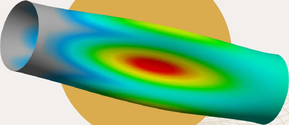
- Linear buckling analysis predicts the stability of elastic structures.
- A structure in a state of stable equilibrium returns to its original position once an applied load is removed.
- Under certain loading conditions, a structure can become unstable. The instability point is reached when the structure continues to deflect without any increase in loading: the structure has buckled.
- Buckling can produce catastrophic failure, even when stresses are below the yield limit.
- FEA lets you verify structural stability, but linear buckling analysis has limitations.
- Buckling can also be a design intent: the steering column of a car is designed to buckle in a crash so the driver is not impaled. Conversely, the foundations of a building are designed not to buckle in compression under its weight.
Linear and nonlinear buckling
Two FEA techniques are available to predict the stability of a structure:
- Linear eigenvalue buckling
- Nonlinear buckling analysis
A linear buckling analysis predicts the theoretical buckling strength of an ideal linear elastic structure (an eigenvalue problem). The classic example of linear eigenvalue buckling is the Euler column: small deflections and no material yielding.
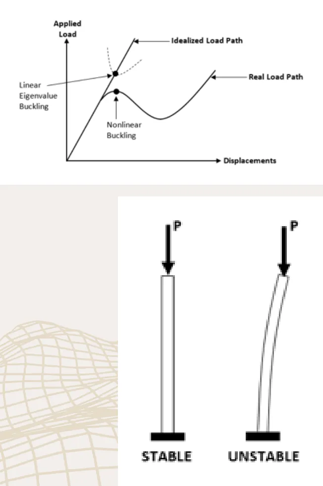
Linear buckling can give non-conservative results and should be used with caution: nonlinear behaviors can prevent a real structure from reaching its theoretical elastic buckling strength. Still, an eigenvalue buckling analysis has two advantages:
- It is a relatively fast analysis, and it gives good information about the stability of the structure.
- The buckled mode shapes can be used as the initial geometric state of a nonlinear buckling analysis, to obtain more realistic results.
Assumptions, limitations and requirements of linear buckling analysis
The following assumptions and limitations apply to linear buckling analysis:
- The deflections of the structure are small.
- The stresses in the structure are elastic.
- Linear buckling analysis does not take into account second-order bending and similar effects.
- The direction of the forces applied to the structure does not change (no follower force effects).
- Only linear elements that support differential stiffness can be used. Refer to the element library in your FEA software manual.
The outcomes of linear buckling analysis
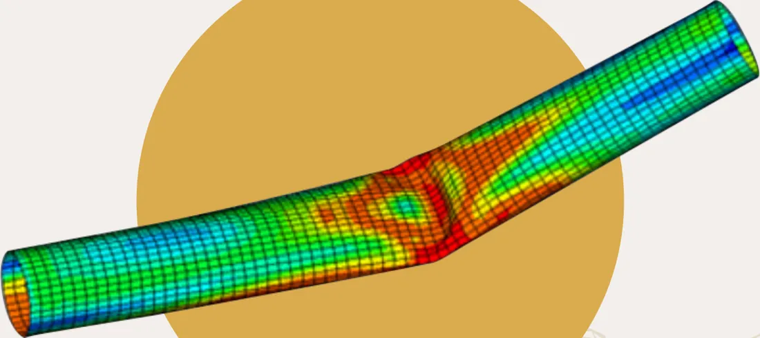
To use linear buckling analysis correctly, you must understand its main outcomes:
- Eigenvalue: in structural analysis, the eigenvalue is called the load factor. To obtain the load that causes the structure to buckle, multiply the applied load by the eigenvalue.
- Shape: how the structure deforms for the given eigenvalue.
- There is one shape for each eigenvalue.
- It shows only where the instability occurs and the appearance of the deformed shape.
- It does not give the real displacements, since they are not computed in a linear buckling analysis.
What linear buckling analysis tells you:
- LBA is a fast check of the stability of your structure.
- Inspecting the buckled shapes tells you whether your model works and behaves as it should.
- It shows the regions of instability (eigenvalue smaller than 1.0).
- It helps you decide where to reinforce the structure.
- The minimum eigenvalue can be incorrect if your structure works in the nonlinear range (geometric or material).
- The minimum positive eigenvalue must be greater than or equal to 1.0 to claim that the analyzed structure will not buckle, and a safety factor must be included to claim stability.
Linear buckling strategy
Everything starts with a linear static analysis
A linear buckling analysis consists of two subcases:
- A linear static analysis
- The computation of the eigenvalues and eigenvectors
Meshing recommendations
The mesh density must be adequate to capture the highest number of half-waves:
- For buckling due to compression, at least five nodes per half-wave are recommended.
- For buckling due to shear, at least ten nodes per half-wave are recommended.
Go further
This Book Byte is taken from Chapter 22 of Practical Finite Element Analysis for Mechanical Engineers by Dominique Madier. The topic is covered in depth, with worked examples, in the on-demand course Practical Basic FEA.
See the Practical Basic FEA course Take the free FEA diagnostic